Learning Objectives
- Identify GPS module components
- Wire the GPS module to Arduino
- Understand serial communication basics
Equipment List (Per Group)
| Component | Quantity | Description |
|---|---|---|
| Arduino Mega 2560 or Uno | 1 | Microcontroller |
| GY-NEO6MV2 GPS Module | 1 | u-blox NEO-6M based |
| Breadboard | 1 | Optional prototyping tool |
| Jumper wires (M-M) | 4+ | For connections |
| USB cable | 1 | Power and programming |
| Laptop with Arduino IDE | 1 | For programming |
💡 Note on Breadboards: For this workshop, we will connect the GPS module directly to the Arduino pins for simplicity and reliability. However, a breadboard is included in your kit if you wish to use it for prototyping or designing more complex systems in the future!
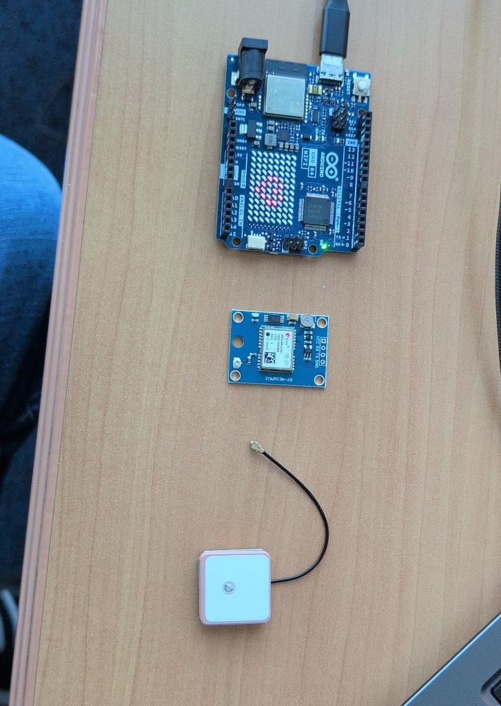
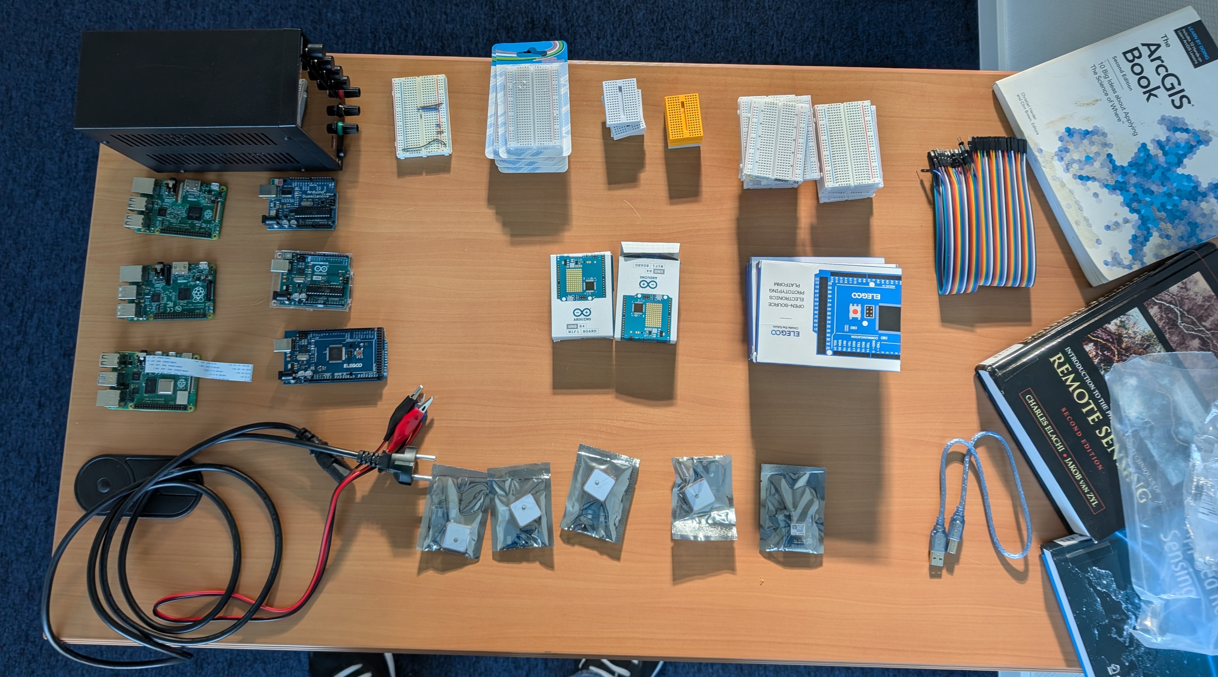
Your kit: Arduino Uno R4 WiFi, NEO-6M GPS Module, and Patch Antenna.
Understanding the GPS Module
GY-NEO6MV2 Specifications
| Feature | Specification |
|---|---|
| Chipset | u-blox NEO-6M |
| Channels | 50 channels |
| Update Rate | 1-5 Hz |
| Position Accuracy | 2.5 m CEP |
| Cold Start | 27 seconds |
| Warm Start | 1 second |
| Voltage | 3.3V - 5V |
| Interface | UART (Serial) |
Module Pins
| Pin | Function | Description |
|---|---|---|
| VCC | Power | Connect to 5V (provides "juice") |
| GND | Ground | Connect to GND (completes circuit) |
| TX | Transmit | GPS "Talks" (connect to Arduino RX) |
| RX | Receive | GPS "Listens" (connect to Arduino TX) |
Reference the labels on the back of your module (VCC, RX, TX, GND).
Antenna Types Comparison
Different GPS applications use different antenna designs. Our NEO-6M module uses a small patch antenna, while professional applications use larger antennas for better accuracy:
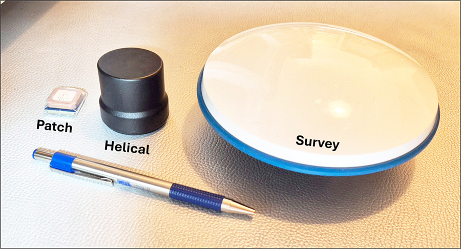
GPS antenna types: Patch (L1 only, cell phones), Helical (L1/L2/L5), Survey-grade (highest precision).
Source: Hodgson, 2025 - GIS&T BoK
Wiring & Assembly
📋 Step-by-Step Assembly Instructions
Follow these steps in order to assemble your GPS receiver:
- Gather your components - Lay out the Arduino, GPS module, jumper wires, and USB cable on your workspace
- Connect the jumper wires - Using 4 male-to-male jumper wires, make the following connections:
- GPS VCC → Arduino 5V (power)
- GPS GND → Arduino GND (ground)
- GPS TX → Arduino Pin 0 (TX)
- GPS RX → Arduino Pin 1 (RX)
- Attach the GPS antenna - Click the small patch antenna connector into the GPS module (you'll hear/feel a small snap)
- Double-check all connections - Verify each wire is firmly seated in the correct pin
- Plug in the USB cable - Connect the USB cable to the Arduino board
- Connect to your computer - Plug the other end of the USB cable into your laptop
- Verify power - The Arduino's power LED should light up. If not, check your connections!
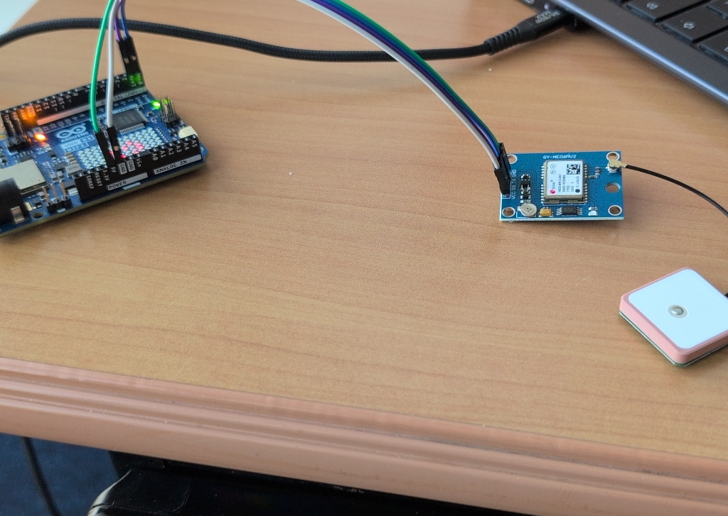
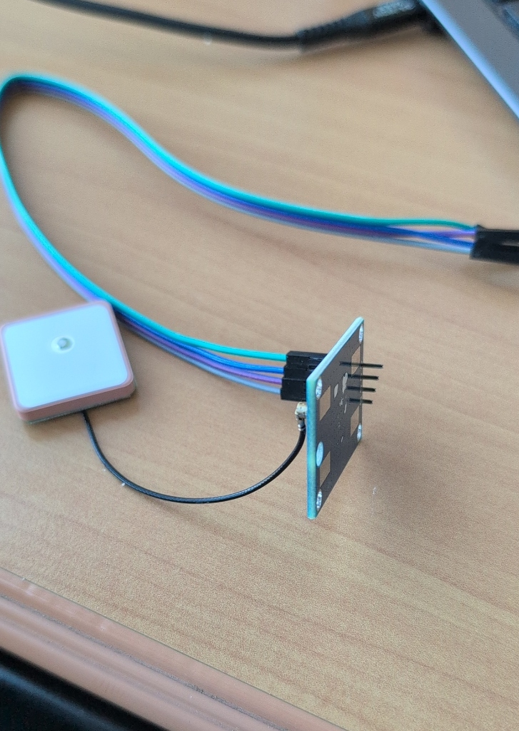
Completed build with Arduino Uno R4 WiFi, NEO-6M module, and patch antenna.
✅ Final Connection Checklist
To make sure it powers on correctly, please double-check these exact spots on your Arduino Uno R4 WiFi:
| GPS Pin | Arduino Pin | Why? |
|---|---|---|
| VCC | 5V | This provides the "juice" to the module. |
| GND | GND | This completes the circuit. |
| TX | Pin 0 (RX) | The GPS "Talks" (TX) and the Arduino "Listens" (RX). |
| RX | Pin 1 (TX) | The Arduino "Talks" (TX) and the GPS "Listens" (RX). |
💡 Power Check
When you plug in the USB cable, you should see the Arduino board light up (power LED turns on). If the board does not light up:
- Check that the USB cable is fully plugged in on both ends
- Try a different USB port on your laptop
- Verify that your wires are connected correctly - an incorrect connection may prevent power
- Make sure VCC goes to 5V and GND goes to GND
Important Notes
- The GPS module needs a clear view of the sky to acquire satellites
- First fix (cold start) can take 1-2 minutes outdoors
- Indoors, you may not get a fix - test near a window or outside
- The module has a small LED that will blink when it has a fix. No blink = no fix.